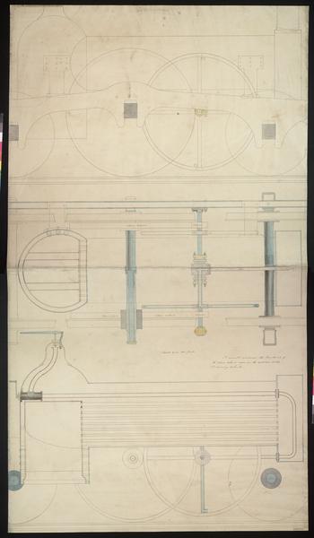
Images Filters Artist William Andrews Collection Collection... Institution of Mechanical Engineers (20) State Library of New South Wales (5) Country Country... England (20) Australia (5) Continent Continent... Europe (20) Oceania (5) Medium No options available Category Category... Travel & Transport (13) Industries & Professions (8) Landscapes & Seascapes (4) Date Date... 1800s (1) 1810s (1) 1820s (1) 1830s (1) 1840s (12) 1850s (10) 1860s (2) 1870s (2) 1880s (5) 1890s (1) William Andrews 25 matching results. See slideshow Sort orderRelevanceOldest additions firstNewest additions firstOldest painted firstNewest painted first See results on a map View map Colonial Architects Office Sydney : interior view, 1886 / possibly by William Andrews (1886) + Add to album Cumberland Street, Sydney ca. 1860-1887 / William Andrews (ca. 1860-1887) + Add to album Windsor Bridge, 1883 / William Andrews (1883) + Add to album Neautral [ie Neutral] Bay, 1883 / William Andrews (ca. 1883) + Add to album Manly [a view, mainly of the beach], 18-- / William Andrews (18--) + Add to album Steam Cylinder and Piston Section (c.1840-1850) + Add to album Steam Cylinder Sections (c.1840-1850) + Add to album Centrifugal Engine, 'drawing no 3', wheel elevation and sections (5th November 1849) + Add to album Andrews Engine, with wheel section (c.1840-1850) + Add to album Andrews Engine, general arrangement (c.1840-1850) + Add to album Centrifugal Engine, wheel elevation (c.1840-1850) + Add to album Centrifugal Engine (c.1840-1850) + Add to album Steam Turbine Locomotive Engine (18th November 1849) + Add to album Detail of a Steam Turbine Locomotive, with side elevation and vertical and longitudinal sections (1848) + Add to album Detail of a Steam Turbine Locomotive, turbine arrangement section and locomotive cross section (1st October 1848) + Add to album Locomotive Engine, longitudinal, horizontal and cross sections (8th August 1859) + Add to album Locomotive Engine, longitudinal section (1850) + Add to album Locomotive Engine, 6ft 6in driving wheel, plan, side elevation and cross sections (15th May 1849) + Add to album Locomotive Engine, 6ft 6in driving wheels, cross sections (3rd April 1849) + Add to album Locomotive Engine, section (c.1840-1850) + Add to album Locomotive Engine, plan and side elevation (c.1840-1850) + Add to album Locomotive Engine, 9ft driving wheel, horizontal and cross sections (1st June 1849) + Add to album Locomotive Engine, 6ft 9in driving wheel, cross section (c.1840) + Add to album Locomotive Tank Engine, 4ft 9in driving wheel, longitudinal section (4th May 1849) + Add to album Locomotive Tank Engine, 4ft 9in driving wheel, plan and section (4th May 1849) + Add to album 1 Colonial Architects Office Sydney : interior view, 1886 / possibly by William Andrews (1886) Courtesy of Dixson Galleries, State Library of New South Wales | Out of copyright Cumberland Street, Sydney ca. 1860-1887 / William Andrews (ca. 1860-1887) Courtesy of Mitchell Library, State Library of New South Wales | Out of copyright Windsor Bridge, 1883 / William Andrews (1883) Courtesy of Mitchell Library, State Library of New South Wales | Out of copyright Neautral [ie Neutral] Bay, 1883 / William Andrews (ca. 1883) Courtesy of Dixson Galleries, State Library of New South Wales | Out of copyright Manly [a view, mainly of the beach], 18-- / William Andrews (18--) Courtesy of Dixson Library, State Library of New South Wales | Out of copyright Steam Cylinder and Piston Section (c.1840-1850) image © Archive, Institution of Mechanical Engineers | All Rights Reserved Steam Cylinder Sections (c.1840-1850) image © Archive, Institution of Mechanical Engineers | All Rights Reserved Centrifugal Engine, 'drawing no 3', wheel elevation and sections (5th November 1849) image © Archive, Institution of Mechanical Engineers | All Rights Reserved Andrews Engine, with wheel section (c.1840-1850) image © Archive, Institution of Mechanical Engineers | All Rights Reserved Andrews Engine, general arrangement (c.1840-1850) image © Archive, Institution of Mechanical Engineers | All Rights Reserved Centrifugal Engine, wheel elevation (c.1840-1850) image © Archive, Institution of Mechanical Engineers | All Rights Reserved Centrifugal Engine (c.1840-1850) image © Archive, Institution of Mechanical Engineers | All Rights Reserved Steam Turbine Locomotive Engine (18th November 1849) image © Archive, Institution of Mechanical Engineers | All Rights Reserved Detail of a Steam Turbine Locomotive, with side elevation and vertical and longitudinal sections (1848) image © Archive, Institution of Mechanical Engineers | All Rights Reserved Detail of a Steam Turbine Locomotive, turbine arrangement section and locomotive cross section (1st October 1848) image © Archive, Institution of Mechanical Engineers | All Rights Reserved Locomotive Engine, longitudinal, horizontal and cross sections (8th August 1859) image © Archive, Institution of Mechanical Engineers | All Rights Reserved Locomotive Engine, longitudinal section (1850) image © Archive, Institution of Mechanical Engineers | All Rights Reserved Locomotive Engine, 6ft 6in driving wheel, plan, side elevation and cross sections (15th May 1849) image © Archive, Institution of Mechanical Engineers | All Rights Reserved Locomotive Engine, 6ft 6in driving wheels, cross sections (3rd April 1849) image © Archive, Institution of Mechanical Engineers | All Rights Reserved Locomotive Engine, section (c.1840-1850) image © Archive, Institution of Mechanical Engineers | All Rights Reserved Locomotive Engine, plan and side elevation (c.1840-1850) image © Archive, Institution of Mechanical Engineers | All Rights Reserved Locomotive Engine, 9ft driving wheel, horizontal and cross sections (1st June 1849) image © Archive, Institution of Mechanical Engineers | All Rights Reserved Locomotive Engine, 6ft 9in driving wheel, cross section (c.1840) image © Archive, Institution of Mechanical Engineers | All Rights Reserved Locomotive Tank Engine, 4ft 9in driving wheel, longitudinal section (4th May 1849) image © Archive, Institution of Mechanical Engineers | All Rights Reserved Locomotive Tank Engine, 4ft 9in driving wheel, plan and section (4th May 1849) image © Archive, Institution of Mechanical Engineers | All Rights Reserved